In VisualApplets example designs are implemented performing geometric transformation, combined geometric transformation and distortion correction and geometric transformation controlled by image moments. The geometric transformation is implemented with target-to-source mapping i.e. inverse. This method is essential to guarantee, that there are no missing pixels in the target image sent to PC [Bur06]. We have implemented inverse geometric transformation on the basis of the operator FrameBufferRandomRead and alternative on the basis of the operator PixelReplicator. The differences will be explained in the following subsections. In these subsections the example designs are introduced in detail.
| Brief Description | |
|---|---|
|
File: \examples\Processing\Geometry\GeometricTransformation\GeometricTransformation_ FrameBufferRandomRead.va |
 |
|
Default Platform: mE5-MA-VCL |
|
|
Short Description Geometric Transformation: rotation, translation, scaling using the operator FrameBufferRandomRead |
|
A geometric transformation is implemented in the VA design "Geometric Transformation_FrameBufferRandomRead.va" with
target-to-source mapping. This method is essential to guarantee, that there are no missing pixels in the target image sent
to PC [Bur06].
The coordinates of the source image
 are calculated with inverse
geometric transformation for all target coordinates
are calculated with inverse
geometric transformation for all target coordinates  .
At the position of the coordinates
.
At the position of the coordinates  the pixel value in
the source image are read with the operator FrameBufferRandomRead at a parallelism of 1. The operator stores each pixel individually in DRAM and
reads one pixel after each other. Linear interpolation helps to correct pixel values in the output image to PC when the
calculated source image coordinates do not match pixel coordinates in the source image.
In Fig. 295 you can see the basic design structure.
the pixel value in
the source image are read with the operator FrameBufferRandomRead at a parallelism of 1. The operator stores each pixel individually in DRAM and
reads one pixel after each other. Linear interpolation helps to correct pixel values in the output image to PC when the
calculated source image coordinates do not match pixel coordinates in the source image.
In Fig. 295 you can see the basic design structure.
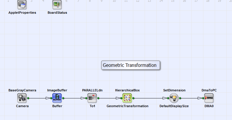
Figure 295. Basic design structure of the VA design "GeometricTransformation_FrameBufferRandomRead.va"
The design consists of a camera interface in Camera Link base configuration (BaseGrayCamera_Camera) and the HierarchicalBox Geometric Transformation in which the scaling, rotation and translation of the acquired images is performed. The operator ImageBuffer_Buffer gives the opportunity to store the image. Via DMA (operator DmaToPC_DMA0) the image is transferred to PC.
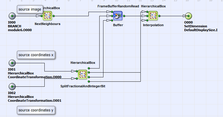
In 296 you can see the content of the HierarchicalBox GeometricTransformation. The parameters IntParamTranslator, FloatParamReference and IntParamReference give you the possibility to set the relevant parameters of the geometric transformation (value of scaling, rotation, translation and image dimensions) very comfortably. The properties are image Height and Width, the number of pixels you want to shift the image in x and y direction (parameter: Translatex and Translatey) and the scale factor in x and y direction Scalex and Scaley. You can set the rotation angle in degrees with the parameter Phi. As alternative you can set these Properties via "Right-Mouse-Click" on the HierarchicalBox GeometricTransformation. You can see the content of this box in Fig. 296.
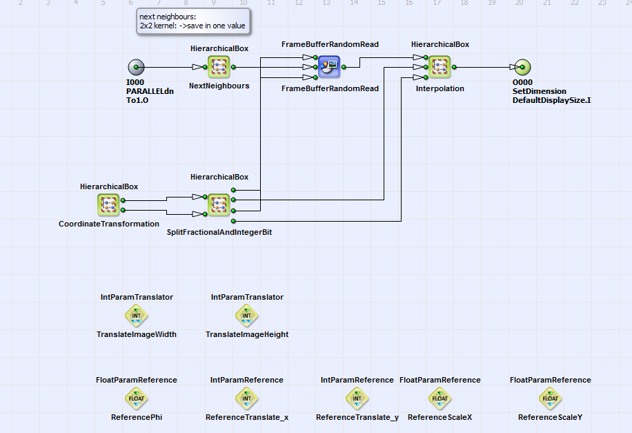
即: SourceImage is linearly written to the buffer FrameBufferRandomRead. With each pixel the next neighbors are saved
in a 2x2 kernel (HierarchicalBox NextNeighbours).
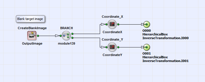
The coordinates of the target image  (eq. 21)
are created with the operators CreateBlankImage, CoordinateX and CoordinateY
in the HierarchicalBox OutputImage (contained in HierarchicalBox CoordinateTransformation)
(see Fig. 297 and 298).
(eq. 21)
are created with the operators CreateBlankImage, CoordinateX and CoordinateY
in the HierarchicalBox OutputImage (contained in HierarchicalBox CoordinateTransformation)
(see Fig. 297 and 298).
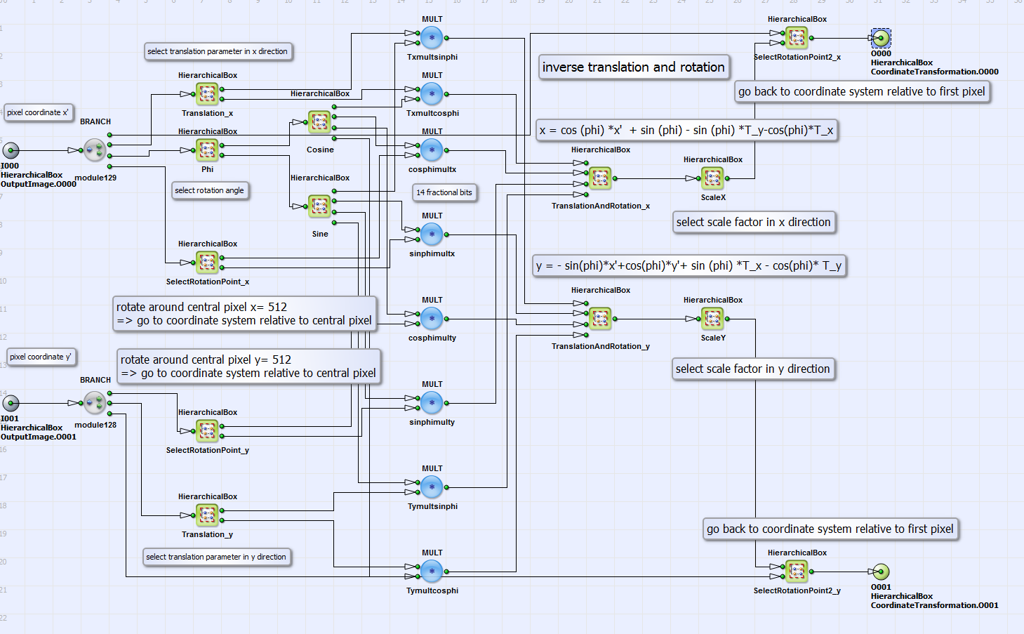
The coordinates  can be rotated, translated and/or scaled in inverse direction according to eq. 21. The rotation angle
 and the parameters
 and
and
 for translation and scaling
can be chosen by setting the corresponding constants via the transport parameters as described above. In Fig.
299 you can see the VA
implementation of eq. 21 with the possibility of additional scaling.
for translation and scaling
can be chosen by setting the corresponding constants via the transport parameters as described above. In Fig.
299 you can see the VA
implementation of eq. 21 with the possibility of additional scaling.
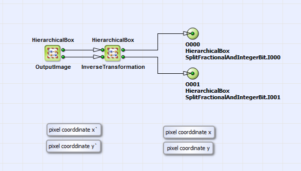
The resulting coordinates of inverse transformation are the source coordinates
 and
and
 (eq. 21). In the HierarchicalBox SplitFractionalAndIntegerBit
(see Fig. 296)
the integer and fractional bit part of these coordinates are separated. The integer bit part, which corresponds to pixel
positions in the source image,
is the coordinate input for the operator FrameBufferRandomRead in x and y direction (see Fig. 296).
This operator reads pixel value information (parallelism = 1) together with its next neighbors (see above) from the source
image at the corresponding coordinates.
The fractional bit part of the source coordinates
(eq. 21). In the HierarchicalBox SplitFractionalAndIntegerBit
(see Fig. 296)
the integer and fractional bit part of these coordinates are separated. The integer bit part, which corresponds to pixel
positions in the source image,
is the coordinate input for the operator FrameBufferRandomRead in x and y direction (see Fig. 296).
This operator reads pixel value information (parallelism = 1) together with its next neighbors (see above) from the source
image at the corresponding coordinates.
The fractional bit part of the source coordinates  and
and
 corresponds to interpixel positions in the source image.
With these informations and the pixel value information from the neighboring pixels in the source image the true pixel value
in the target image is bilinear
interpolated in the HierarchicalBox Interpolation. Please see for detailed description for the interpolation process [Bur06].
corresponds to interpixel positions in the source image.
With these informations and the pixel value information from the neighboring pixels in the source image the true pixel value
in the target image is bilinear
interpolated in the HierarchicalBox Interpolation. Please see for detailed description for the interpolation process [Bur06].
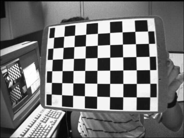
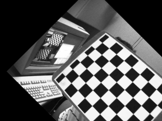
In Fig. 300 and 301 you can see for an example geometric transformation the source and target images. A translation of 100 pixels in x and y direction and a rotation around 45° is performed.
| Brief Description | |
|---|---|
|
File: \examples\Processing\Geometry\GeometricTransformation\GeometricTransformation_ImageMoments.va |
 |
|
Default Platform: mE5-MA-VCL |
|
|
Short Description Geometric Transformation: rotation and translation of an object into the image center using image moments |
|
In this example design the position and rotation angle of an object in a RGB image is determined with image moments. A rotation into a horizontal orientation and a translation into the image center is performed. As default the input image dimension is 640x240 pixels and the output image dimension 256x128 pixels. In Fig. 302 you can see the basic design structure.
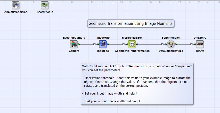
The design consists of an RGB camera interface in Camera Link base configuration (BaseRgbCamera_Camera) and the HierarchicalBox Geometric Transformation in which the rotation and translation of the acquired images is performed. With "right-mouse-click" under "Properties" you can set the input and output image dimensions and the binarization threshold. This threshold is relevant for the calculation of the image moments as described below. The geometric transformation is done with target-to-source mapping (see introduction text in section ). Via DMA (operator DmaToPC_DMA0) the image is transferred to PC. In Fig. 303 you can see the content of Geometric Transformation.
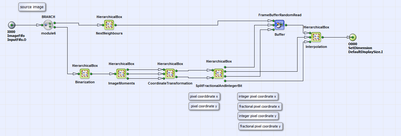
The rotation angle relative to the horizontal position and the center of gravity position of the object is determined with image moments in the HierarchicalBox ImageMoments calculated on the binarized image (HierachicalBox Binarization). The content of ImageMoments is equivalent to the box ImageMoments of the VA example "ImageMoments.va" (see Fig. 323 in section ) but without the calculation of the object eccentricity. The output links of the HierachicalBox ImageMoments (from up to down) are the center of gravity position in x and y direction and the rotation angle. The source coordinate calculation (according to eq. 21) based on these parameters is content of the HierachicalBox CoordinateTransformation. In 304 you can see the content of this box.
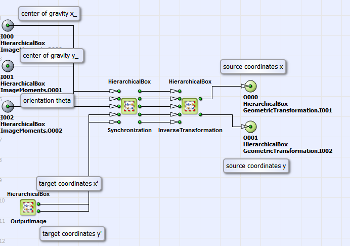
In the HierarchicalBox 同步方式 the single pixel values of center of gravity in x and y direction and rotation are extended to output image
dimension, which is defined in the HierarchicalBox OutputImage. The output links of this box represent the target image coordinates
 . In the HierarchicalBox
InverseTransformation the source coordinates
. In the HierarchicalBox
InverseTransformation the source coordinates
 and
and
 are calculated according to eq.
21. In Fig. 305
you can see the content of this box.
are calculated according to eq.
21. In Fig. 305
you can see the content of this box.
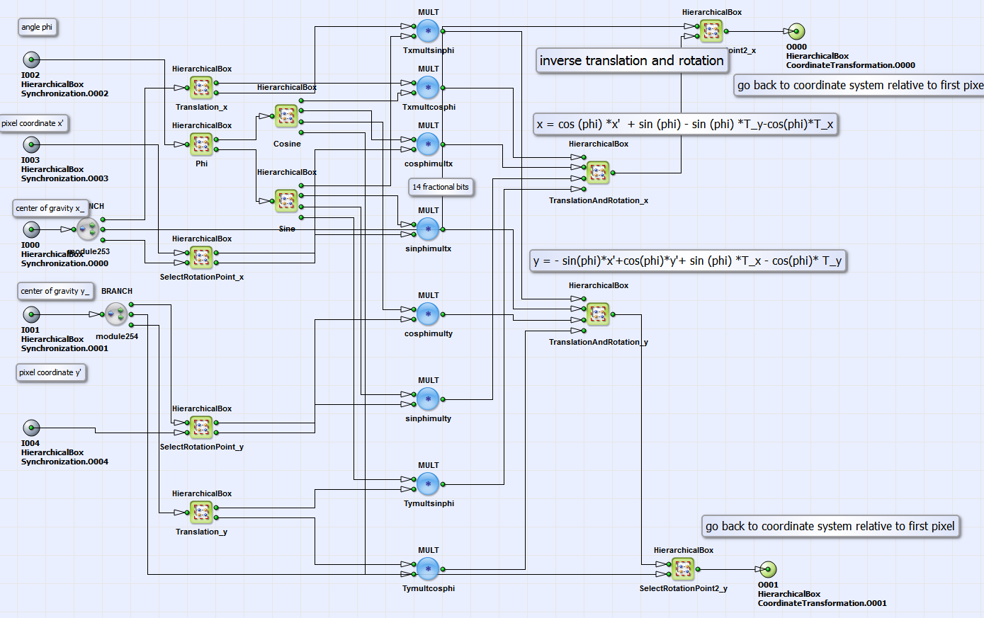
The design structure in this box is similar to the implementation of inverse transformation in the examples "GeometricTransformation_FrameBufferRandomRead.va"
and "GeometricTransformation_PixelReplicator.va". The difference is, that the translation parameter in x and y direction
is determined by the difference between
the center of gravity and the image center in x and y direction (see content of boxes Translation_x and Translation_y).
The rotation angle (content of box Phi) is defined by the result of the image moments calculation.
Coming back to the basic design structure in Fig. 302. The calculated source image coordinates
 and
and
 represent the output links of
box CoordinateTransformation. In the box GeometricTransformation
(see Fig. 306) the geometric transformation with the operator
FrameBufferRandomRead and the bilinear interpolation of the correct target pixel value is performed analog to the example
"GeometricTransformation_FrameBufferRandomRead.va" (see Fig. 296 in section
).
represent the output links of
box CoordinateTransformation. In the box GeometricTransformation
(see Fig. 306) the geometric transformation with the operator
FrameBufferRandomRead and the bilinear interpolation of the correct target pixel value is performed analog to the example
"GeometricTransformation_FrameBufferRandomRead.va" (see Fig. 296 in section
).
For an example object in Fig. 307 you can see the orientation and position corrected target image in Fig. 308.

| Brief Description | |
|---|---|
|
File: \examples\Processing\Geometry\GeometricTransformation\GeometricTransformation_PixelReplicator.va |
|
|
Default Platform: mE5-MA-VCL |
|
|
Short Description Geometric Transformation: rotation, translation, scaling using the operator PixelReplicator |
|
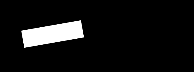
The VisualApplets design example "GeometricTransformation_PixelReplicator.va" performs the same geometric transformation as the example "GeometricTransformation_FrameBufferRandomRead.va" but with higher performance. As explained above the operator FrameBufferRandomRead stores each pixel individually in DRAM and reads them one after each other. In this example a block of a certain amount of pixels is stored in a DRAM cell. The example design reads only from DRAM if the pixel to be read is not in the same cell as the previous pixel. The example in Fig. 309 with 8 pixel per DRAM cell gives an idea of the performance increasement.
The DRAM blocks are marked in green. To read the 9 pixels a to i you need 3 DRAM cycles instead of 9. We achieve an effective parallelism of 3 here. The maximum amount of 8 bit pixel, which can be stored in one RAM cell, is 32 (marathon VCL data width: 256 Bit). The shape of the ROI for RAM cell block is defined by the rotation angle of the geometric transformation. As default a RAM cell shape of 9x3 pixels is chosen in this example. The basic design structure is equivalent to the design structure in Fig. 295 but without the operator PARALLELdn_To1. The content of the HierarchicalBox GeometricTransformation is also equivalent to the corresponding box (Fig. 296) in the example "GeometricTransformation_FrameBufferRandomRead.va". The difference is that the operator FrameBufferRandomRead is replaced by the HierarchicalBox FrameBufferRandomRead_Par8. You can see its content in Fig. 310.
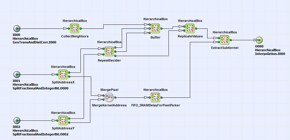
In the box CollectNeighbors the source image is split into sub-ROIs, which define the size of each RAM cell. Here a RAM cell size of 9x3 is chosen. In
the
HierarchicalBoxes SplitAdressX and SplitAdressY the integer bit part of the source coordinates
 and
and
 as result of inverse geometric transformation (see section
) is split in two components. The upper bit part (upper output link of
SplitAdressX and SplitAdressY) represents the position of the DRAM cell, the lower bit part represents the pixel position in the
DRAM cell. A DRAM cell is read at the DRAM cell coordinates in the HierarchicalBox Buffer (contains operator FrameBufferRandomRead) if it was not decided
in the HerarchicalBox RepeatDeciderto reuse previous DRAM cell. If it is decided to reuse the previous cell, the pixel values of the DRAM cell need to be replicated.
This is
performed in the HierarchicalBox ReplicateValues with the operator PixelReplicator. In the box ExtractSubKernel the required pixel value
together with its next neighbors is extracted from DRAM cell using pixel coordinates as output of SplitAdressX and SplitAdressY (lower output link).
The bilinear interpolation of the correct target pixel value is performed equivalent to the example in .
as result of inverse geometric transformation (see section
) is split in two components. The upper bit part (upper output link of
SplitAdressX and SplitAdressY) represents the position of the DRAM cell, the lower bit part represents the pixel position in the
DRAM cell. A DRAM cell is read at the DRAM cell coordinates in the HierarchicalBox Buffer (contains operator FrameBufferRandomRead) if it was not decided
in the HerarchicalBox RepeatDeciderto reuse previous DRAM cell. If it is decided to reuse the previous cell, the pixel values of the DRAM cell need to be replicated.
This is
performed in the HierarchicalBox ReplicateValues with the operator PixelReplicator. In the box ExtractSubKernel the required pixel value
together with its next neighbors is extracted from DRAM cell using pixel coordinates as output of SplitAdressX and SplitAdressY (lower output link).
The bilinear interpolation of the correct target pixel value is performed equivalent to the example in .
| Brief Description | |
|---|---|
|
File: \examples\Processing\Geometry\GeometricTransformation\GeometricTransformation_ DistortionCorrection.va |
 |
|
Default Platform: mE5-MA-VCL |
|
|
Short Description Geometric Transformation: rotation, translation, scaling, distortion and Keystone correction using the operator PixelReplicator |
|
The VA example "GeometricTransformation_DistortionCorrection.va" is an extension of the design "GeometricTransformation_PixelReplicator.va". In addition distortion and Keystone correction (according to eq. 22 and eq. 23) is implemented in this design. In the following only the different parts in comparison to "GeometricTransformation_PixelReplicator.va" will be explained. In Fig. 311 you can see the basic design structure.
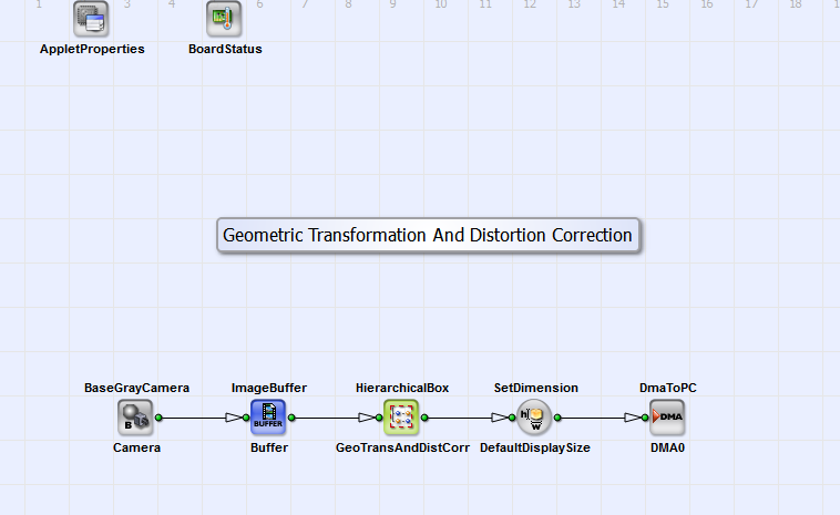
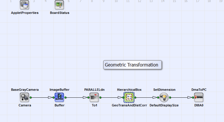
Figure 311. Basic design structure of the VA design "GeometricTransformation_DistortionCorrection.va"
A grayscale image (maximum dimension: 4096x4096 pixels) from a camera interface in CameraLink base configuration (BaseGrayCamera_Camera) is transformed in the HierarchicalBox GeoTransAndDistCorr and transferred to PC via DMA (DmaToPC_DMA0). The structure is equivalent to the design "GeometricTransformation_FrameBufferRandomRead" and "GeometricTransformation_PixelReplicator". The structure of GeoTransAndDistCorr is equivalent to the box GeometricTransformation of the same two designs (see Fig. 296). Here the inverse transformation and in addition distortion and Keystone correction is performed. The content of box CoordinateTransformation (in box GeometricTransformation) is shown in Fig. 312.
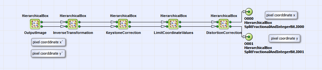
Equivalent to the designs "GeometricTransformation_FrameBufferRandomRead" and
"GeometricTransformation_PixelReplicator" (sections and
) the target coordinates
 are inverse transformed according to eq.
21 with additional scaling (see also section
).
With the resulting coordinates of inverse transformation we perform then a inverse Keystone and distortion correction in
the HierarchicalBoxes
KeystoneCorrrection and DistortionCorrection. The content of these boxes are displayed in Fig.
313 and Fig.
312.
are inverse transformed according to eq.
21 with additional scaling (see also section
).
With the resulting coordinates of inverse transformation we perform then a inverse Keystone and distortion correction in
the HierarchicalBoxes
KeystoneCorrrection and DistortionCorrection. The content of these boxes are displayed in Fig.
313 and Fig.
312.
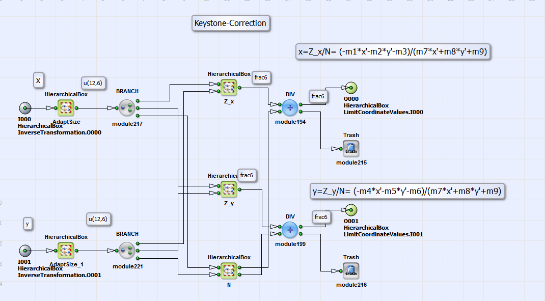
In these boxes eq. 22 and
eq. 23 are implemented. The matrix elements m1 to m9 in the boxes
Z_x, Z_y and N (see Fig. 313)
can be calculated with the help of the OpenCV library [Ope16b]. For the example image "Example.tif"
(under \examples\Processing\Geometry\GeometricTransformation) you find the example matrix values in the text file "MatrixValues.txt"
at the same location.
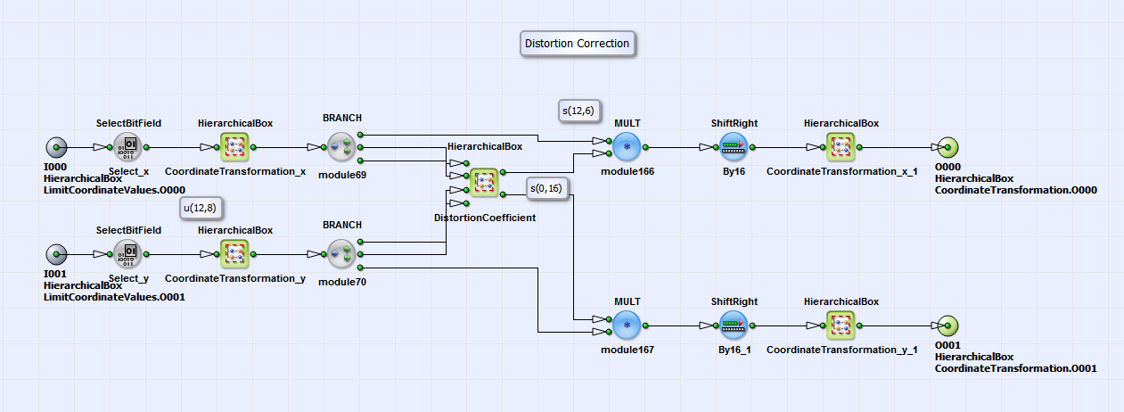
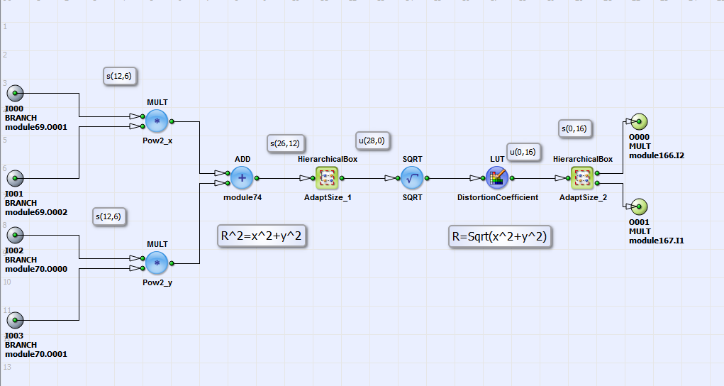
For the distortion correction in Fig. 312 first the coordinates are transformed
in a coordinate system relative to the optical center (CoordinateTransformation_x and CoordinateTransformation_y),
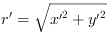
which is in most cases the image center. In the HierarchicalBox DistortionCoefficient the distance
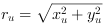 (see eq. 23) from optical center is calculated. For every
 then a distortion correction
parameter
then a distortion correction
parameter  exists in a lookup table (see Fig.
315).
The lookup-table is externally created with a Matlab module, which you can find under \examples\Processing\Geometry\GeometricTransformation
\LUTDistortionCorrection.m and the distortion parameters
exists in a lookup table (see Fig.
315).
The lookup-table is externally created with a Matlab module, which you can find under \examples\Processing\Geometry\GeometricTransformation
\LUTDistortionCorrection.m and the distortion parameters
 and
and
 created with the OpenCV library [Ope16b]. In "LUTDistortionCorrection.m" you find as example the correction parameters
 and
and
 for the example image "Example.tif" (under \examples\Processing\Geometry\GeometricTransformation) [Ope16a].
The coefficient
for the example image "Example.tif" (under \examples\Processing\Geometry\GeometricTransformation) [Ope16a].
The coefficient  is then multiplied with coordinates
 and
and
 (Fig.
312). The resulting distorted
coordinates are then transformed back to a coordinate system relative to the "left upper image
corner" (see boxes CoordinateTransformation_x and CoordinateTransformation_y). The
result are the source image coordinates
(Fig.
312). The resulting distorted
coordinates are then transformed back to a coordinate system relative to the "left upper image
corner" (see boxes CoordinateTransformation_x and CoordinateTransformation_y). The
result are the source image coordinates  and
and
 . The content of the HierarchicalBox
LimitCoordinateValues (Fig. 312)
sets boundary conditions for the transformed image coordinates. After separation of integer and fractional bit parts
(see box SplitFractionalAndIntegerBit in Fig. 296) the pixel values at the calculated
corresponding integer source image coordinates are read from source image.
The fractional bit part is used for bilinear interpolation (see Interpolation) according to [Bur06]
in order to correct the pixel values in the output image due to interpixel positions in the source
image. Via DMA the signal is transferred to PC.
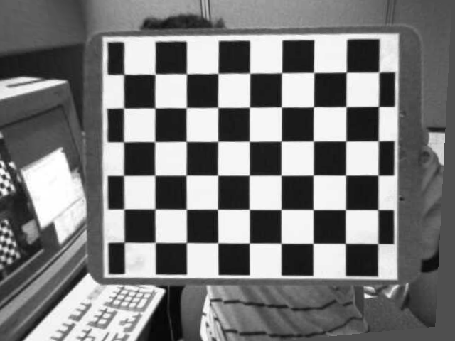
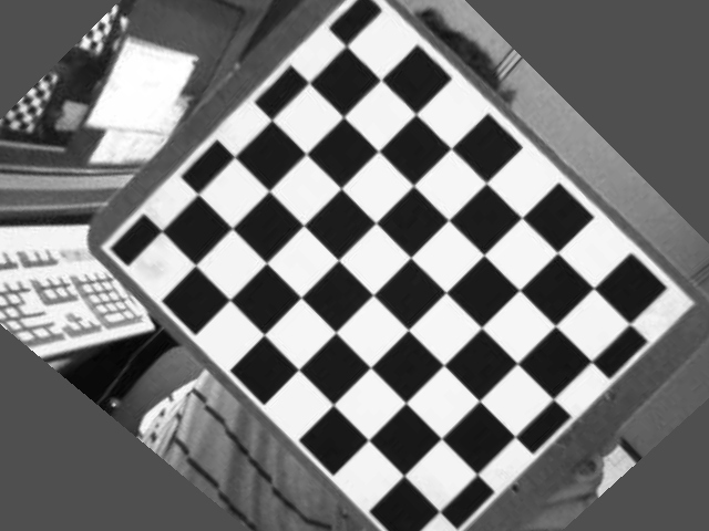
For demonstration purpose you can see in Fig. 316,
317 and
318 the distorted source image, the
Keystone and distortion corrected target image and a rotated and distortion corrected target image.
. The content of the HierarchicalBox
LimitCoordinateValues (Fig. 312)
sets boundary conditions for the transformed image coordinates. After separation of integer and fractional bit parts
(see box SplitFractionalAndIntegerBit in Fig. 296) the pixel values at the calculated
corresponding integer source image coordinates are read from source image.
The fractional bit part is used for bilinear interpolation (see Interpolation) according to [Bur06]
in order to correct the pixel values in the output image due to interpixel positions in the source
image. Via DMA the signal is transferred to PC.
For demonstration purpose you can see in Fig. 316,
317 and
318 the distorted source image, the
Keystone and distortion corrected target image and a rotated and distortion corrected target image.

| Brief Description | |
|---|---|
|
File: \examples\Processing\Geometry\GeometricTransformation\DistortionCorrection.va |
 |
|
Default Platform: mE5-MA-VCL |
|
|
Short Description In this example design a distortion correction is implemented. |
|
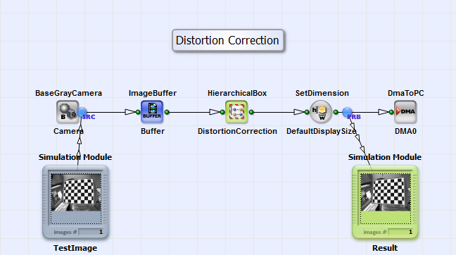
In the design "DistortionCorrection.va" a distortion correction according to eq. 22 is implemented. It is analog to the one in the design "GeometricTransformation_DistortionCorrection.va" but without performing geometric transformation and keystone correction. You can see the basic design structure in Fig. 319.

The design consists of an interface for a grayscale camera in Camera Link base configuration, a buffer module, the HierachicalBox DistortionCorrection and the DmaToPC. The distortion correction of the grayscale image is performed in DistortionCorrection. You can see its content in Fig. 320.
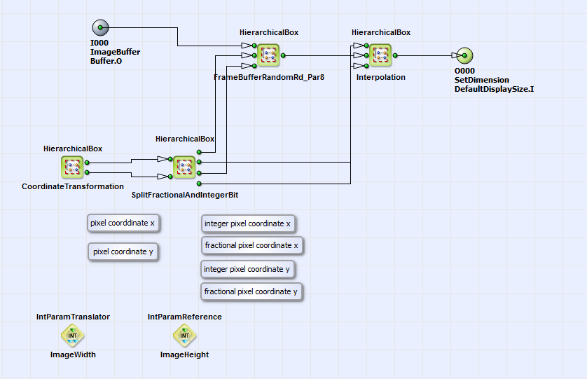
The structure is analog to the content of the HierarchicalBox GeometricTransformation (see
Fig. 296) in the design "GeometricTransformation_PixelReplicator.va" of
section . The operator FrameBufferRandomRead is replaced
by the HierarchicalBox FrameBufferRandomRd_Par8 as also done in "GeometricTransformation_PixelReplicator.va" and "GeometricTransformation_DistorationCorrection.va"
(see sections and
). The source image is linearly written to the buffering element
FrameBufferRandomRd_Par8. In this module also the three next neighbors are stored together with each pixel (see box CollectNeighbors in box
FrameBufferRandomRd_Par8). In box CoordinateTransformation/ OutputImage the target image coordinates
 are created using the operators CreateBlankImage,
CoordinateX and CoordinateY. These coordinates are transformed according to eq. 22 to
the source image coordinates
are created using the operators CreateBlankImage,
CoordinateX and CoordinateY. These coordinates are transformed according to eq. 22 to
the source image coordinates  in the HierarchicalBox
InverseCorrection (see box CoordinateTransformation). You can see its content in Fig. 321.
in the HierarchicalBox
InverseCorrection (see box CoordinateTransformation). You can see its content in Fig. 321.
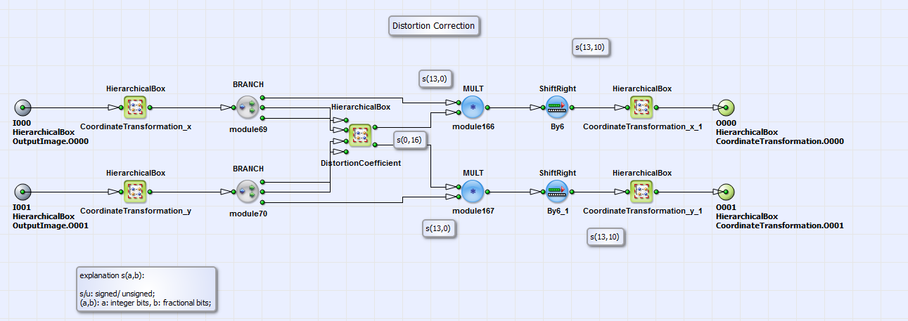
It is equivalent to the implementation of box DistortionCorrection of "GeometricTransformation_DistortionCorrection.va" (see Fig.
314). For each target image radius
 relative to the image center a lookup table value
C_r is selected in the HierarchicalBox DistortionCoefficient. C_r is multiplied with the target image coordinates
relative to the image center a lookup table value
C_r is selected in the HierarchicalBox DistortionCoefficient. C_r is multiplied with the target image coordinates
 according to eq. 22
and transformed back to a coordinate system relative to first pixel (see CoordinateTransformation_x_1 and CoordinateTransformation_y_1). As you can see in
Fig. 320 the resulting source coordinates are split in an integer and fractional part in the box
SplitFractionalAndIntegerBit. The integer part is used to read the pixels of the source image at the corresponding source image coordinates and the fractional
part is used for bilinear interpolation of the final result. The distortion corrected image is the transferred via DMA
to PC.
according to eq. 22
and transformed back to a coordinate system relative to first pixel (see CoordinateTransformation_x_1 and CoordinateTransformation_y_1). As you can see in
Fig. 320 the resulting source coordinates are split in an integer and fractional part in the box
SplitFractionalAndIntegerBit. The integer part is used to read the pixels of the source image at the corresponding source image coordinates and the fractional
part is used for bilinear interpolation of the final result. The distortion corrected image is the transferred via DMA
to PC.
